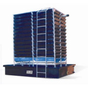
U TUBE FINNED TUBE HEAT EXCHANGER
RANGE OF EXPERIMENTS TO BE CARRIED OUT:
1. To determine Heat transferrate of heating & cooling.
2. To determine the overall andindividual film heat transfer
3. To calculate Effectiveness of the Heat Exchanger.
4. The experiments can be conductedat various values of input &
calculation can be made accordingly.
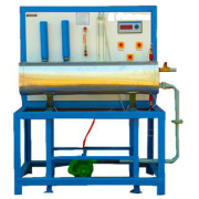
TECHNICAL DESCRIPTION :
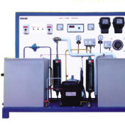
The shell and tube type u tube finned tube heat exchangerThe apparatus consists of a Shell and Tube type heat exchanger.
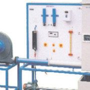
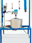
The hot fluid is hot water which is obtained from an electrical geyser & it flows through the Shell. While the cold fluid is air , flowing through the tube The flow rate of hot Water water is measured by using rotameter.The flow rate of air measured by using manometer Temperatures at inlet and outlet are measured by using thermocouples and temperature indicator.
DIMENSIONS AND WEIGHT :
Size :1.2 m.(L)x 1 m(W) X 2m ( H )
Weight :Approx. 100 Kg , Water: @10 Lpm
SERVICE REQUIRED :
230 v Ac Supply 50 Hz,Single Phase.
SCOPE OF DELIVERY:
1. Experimental Setup
2. Instructional Manual
OPTIONAL FACILITY: Data logging Facility
Get More Details:- 31- U TUBE FINNED TUBE HEAT EXCHANGER