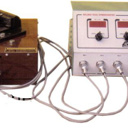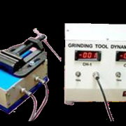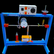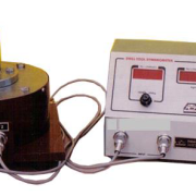
DRILL TOOL DYNAMOMETER
RANGE OF EXPERIMENTS TO BE CARRIED OUT:
1. To Study the Effect of speeds and feeds on the action of cutting tool.
2. To Study the Effect of Mechanical properties of work material on cutting forces.
3. To observe the Values of forces exerted on machine components on jigs and fixtures, and effect of these forces on the geometrical accuracy of the work pieces.
TECHNICAL DESCRIPTION:
This is a armed wheel type strain guage drill tool dynamometer designed to measure thrust & torque during drilling operation. This dynamoneter is sutiable for drilling a hole up to 25 mm size in Mild Steel. With this dynamometer students can study the change in these forces by varying speed, Cut & feed.
DIMENSIONS AND WEIGHT :
Size :0.3 m.(L)x 0.3 m(W) X 0.3m ( H )
Weight :Approx. 5 Kg
SERVICE REQUIRED : 230 v Ac Supply 50 Hz
SCOPE OF DELIVERY:
1. Experimental Setup
2. Instructional Manual
OPTIONAL FACILITY: Data logging Facility
Get More Details:- 21 -DRILL TOOL DYNAMOMETER